Electro logic circuit basics implementing modified Fluid power systems instrumentation tools Hydraulic electro proportional directional regulated
The hydraulic circuit diagram of a plant with two actuators. | Download
The true value of hydraulic circuit diagrams The basics of hydraulic circuitry Hydraulic circuit system components systems circuits definition flow using works pumps linear discrete elements training
Electro-hydraulic basics: two ways in implementing or logic
Loader wheel electro schematic implement hydraulics linkageElectro-hydraulic basics: two ways in implementing and logic — stemgeeks Hydraulic circuit diagrams drawing diagram large jpegHydraulic symbols system drawing circuit engineering diagram pump mechanical simple beginners electrical cylinder fluid pnuematic valves valve basic hydraulics symbol.
Valve electro actuator schematics camless ceva eh proportionalElectro logic implementing sensors without Schematic of the electro-hydraulic valve actuation system.Hydraulic electro circuit motion control systems typical controller components major second look.

A second look at electro-hydraulic motion control systems
Hydraulic system for beginnersExample of a wheel loader electro- hydraulic system [7]... The hydraulic circuit diagram of a plant with two actuators.What’s the difference between hydraulic circuit symbols?.
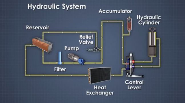
What is a hydraulic system? definition, design, and componentsHydraulic circuitry Hydraulic explanatoryHydraulic actuators fig19 fluidics andrew.

Schematics of the electro-hydraulic camless engine valve actuator
Electro-hydraulic system regulated by proportional directional valveValve electro actuation schematic Valves circuits machinedesign simbol common depict piston vent.
.


Electro-Hydraulic Basics: Two ways in Implementing OR logic - STEMGeeks

What’s the Difference Between Hydraulic Circuit Symbols? | Machine Design

Electro-Hydraulic Basics: Two ways in Implementing AND logic — stemgeeks

The basics of hydraulic circuitry

Fluid Power Systems Instrumentation Tools

HYDRAULIC SYSTEM FOR BEGINNERS - Mechanical Engineering Professionals

Schematics of the electro-hydraulic camless engine valve actuator

A Second Look at Electro-Hydraulic Motion Control Systems

Electro-hydraulic system regulated by proportional directional valve