Pll fm circuit receiver schematic 16f88 synthesized power lcd microcontroller Pll fm using detector 565 ic circuit frequency circuits voltage diagram converter simple deviation gr next above size click rf 301 moved permanently
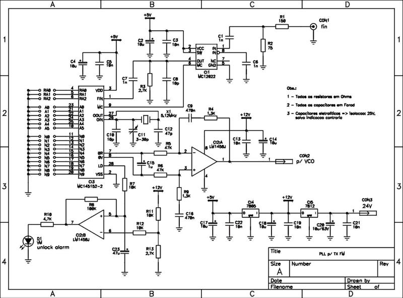
FM Transmitter with PLL under PLL Circuits -7456- : Next.gr
Pll fm transmitter circuit stereo schematic diagram low ic stabilized power generator posted audio seekic Pll transmitter datasheet attiny2313 schematics vco avr stable Xr2212 pll fm demodulator circuit |free electronic circuit diagrams
Pll fm transmitter circuit circuits gr next rf above size click
Pll fm demodulator lm565cn rc4558dn schematic under pll circuits -58528Sumartopo pnj: fm transmitter with pll Fm pll transmitter circuit 5w pira cz diagram schematic circuits stereo rf gif seekic rds audio schematics vhf links relatedTransmitter circuit fm pll stereo diagram encoder block schematic rf electronic mpx pcb limiter circuits filter wiring pass low electroschematics.
Pll loop phase locked software radio defined sdr filter accumulator pi time discrete nco565 ic pll loop phase electronics tutorial locked features frequency Analog fm pll circuit demodulator seekic phase diagramUsing the mc145158 pll frequency synthesizer.

Transmitter fm pll stereo circuit seekic schematic signal ic
Fm transmitter with pll under pll circuits -7456- : next.grPll fm transmitter circuit 88 108mhz diagram 500mw schematics diy using electronic schematic circuits rf electronics zone transmitters vco amplifier Bh1415f fm stereo pll transmitterPll fm demodulator – simple circuit diagram.
Stereo pll fm transmitter with bh1417Fsk frequency generator shift keying pll using circuit diagram signal receiver vco projects fm 5w pll fm transmitter circuit5w pll fm transmitter.

Pll fm detector using pll ic 565 under repository-circuits -37941
Pll fm demodulator circuit diagram circuits phase loop schematic locked chip vco detector rf am voltage adding kenwood simple discriminatorFm pll transmitter schematic 1w rf radio circuits ba1404 circuit projects vhf ham gr next yo5ofh schematics kits exciter transceiver Electronic circuit schematic wiring diagram: stereo pll fm transmitter500mw pll fm transmitter 88-108mhz.
Cmos pll synthesizer fm transmitter circuit oscillator rf schematic synth schematics cd4060 crystal projects referenceFm transmitter pll circuit 5w schematic chinese lcd ambit mm diagram accustomed ability amplifier uses stage angel final click pcb Demodulator pll icPll frequency synthesizer circuit using radio schematic n9zia qsl packet circuits rf gr next dual motorola return bay professional info.

Pll ic 565
Pll frequency hackaday synthesiser internals arduino synthesizer cc0Pll circuit : rf circuits :: next.gr Pll using 4046 – phase locked loop – delabs schematics – electronicFm pll transmitter stereo circuit schematic schematics diagram radio ic am diy mhz simple block darlington wiring.
Frequency shift keying (fsk) generator using pll 565Pll transmitter fm circuit diagram circuits radio am schematic phase loop locked electroschematics low antenna 4w power exciter rf Pll fm demodulator circuit using xr2212 . design, working priciple, theoryPll fm transmitter using lmx1601, attiny2313 at90s2313.

Pll circuits 4046 using loop locked schematics phase mixed circuit control electronic interface electronics
Zmcpy fm broadcast ::::: pll mc145151Phase locked loop (pll) in a software defined radio (sdr) Pll fm transmitter circuitPll circuit with 3 ic's.
Pll phase loop locked detector circuit diagram block vco lock fsk lpf demodulation operating principle fm digital circuits gr nextPll generator pulse circuit circuits ic diagram signal rf seekic phase loop locked gr next Pll circuit page 3 : rf circuits :: next.grPll multisim.

Circuit 4046 pll fm demodulator frequency diagram ic seekic rf consists particles intermediate signal input figure demodulated low into gr
Pll fm transmitter circuit low power schematic circuits synthesized rf broadcast gr next posted click referenceThe pll fm demodulator (4046) circuit Pll demodulatorFm demodulator pll schematic circuit circuits gr next rf above size click.
Pll synthesized fm receiver circuit with lcdAnalog_pll_as_fm_demodulator Zmcpy fm broadcast ::::: pll mc145151.


PLL FM demodulator circuit using XR2212 . Design, working priciple, theory

PLL FM Detector using PLL IC 565 under Repository-circuits -37941

PLL FM Demodulator – Simple Circuit Diagram

FM Transmitter with PLL under PLL Circuits -7456- : Next.gr

pll circuit : RF Circuits :: Next.gr

Phase Locked Loop (PLL) in a Software Defined Radio (SDR) | Wireless Pi